|
| Next Page | Main Description | Previous Page |
| 1 | 2 | 3 | 4 | 5 | 6 | 7 | 8 | 9 | 10 | 11 |
The purpose of the project was to construct a substation to enable three plants owned by the same company to purchase power at transmission level voltage (115 KV). The plants were serviced at 17.2 KV and fed at three different locations. The objective of the project was to combine these three services and to feed them from the new substation. It was also desired to monitor the power quality and usage of each of these plants so that the bill could be allocated automatically at the end of each month. The peak combined load was about eight megawatts.
The scope of the project was to provide complete engineering, design, budgeting, bid specifications, construction specifications, construction management, testing and startup in a very short timeline. It was also required to do all negotiations with Pacific Gas and Electric (PG&E), the California Public Utilities Commission (CPUC), BNSF Railroad, the local building department and all environmental agencies. A "Negative Declaration" had to be completed and a permit from the CPUC had to be obtained. The permit from the CPUC required satisfying all environmental concerns as well as concerns of residential neighbors about Electromagnetic Fields (EMF).
A requirement was made to provide, install and commission a Supervisory Control And Data Acquisition (SCADA) system to monitor all power usage and quality. It also monitored over 100 digital and analog I/O points both inside the substation and at each of the three services. The digital input points included alarms in the transformer, protective relays, circuit breakers and the control cabinet as well as the statuses of these devices. The digital output points included the capacitor banks control. The analog input points included CTs, PTs, transformer oil temperature, transformer oil level and three transformer winding temperatures. The system consisted of one Master Display Server (MDS) connected to five digital instrumentation packages remotely located in the control cabinets. The SCADA system equipment was provided by Power Measurements, Ltd. and included a 3720 at each of the three metering locations, a 7700ion and a 3800 RTU in the substation. The MDS was on a Windows NT Platform with Pegasys Software. ABB metering class CTs and PTs were used. An algorithm in the SCADA system was developed to control the substation capacitor bank.
The distance from the substation to the MDS was about 5,000 feet. The routing included going overhead and underground. There was a concern about running copper wire out of the substation because of what damage a ground Potential Rise (GPR) in the substation could cause at a point outside of the substation. Fiber Optic Communications was chosen for this reason. A 24 strand Siecor Fiber Optic Cable was chosen to allow for a RS485 Network between the power monitoring equipment, telecommunications to the substation and future communications between two plants. Fiber Optic Communications including all cable, connections, installation and testing was performed by a Siecor "Extended Warranty Contractor".
Existing distribution facilities were purchase form PG&E. The overhead 17.2KV pole line was rebuilt with new conductors and insulators. Defective poles were replaced. A unique option was negotiated with PG&E to allow for an emergency back-tie at the point of old service interconnect. A new pole line was constructed to tie in the main plant. The main plant was protected by a Cooper Recloser. In order for the main plant to be connected to this new pole line, without tearing out an excessive amount of concrete, a 600 foot directional drill with a 12 inch steel encasement was done. The contractor drilled from the end of the pole line under railroad tracks to the substation in the main plant. A 500MCM, 35KV Class Cable was installed in the encasement along with the Fiber Optic Cable. Switches were installed on the pole line at various points to allow for isolation of a problem without interrupting power to the other services. Lightning protection was installed at various points on the pole line.
Modesto Irrigation District (MID) made a proposal to take over service from PG&E. MID provides transmission service at 69KV while PG&E provides transmission service at 115KV. The company wasn�t sure if they wanted to change to MID, so it was decided to purchase a transformer with a dual voltage primary. A 12MVA 120X69-17.2KV transformer was purchased from Waukesha Electric. The transformer had cover bushings with CTs for overcurrent and differential relay protection. A nitrogen preservation system was installed. The transformer had a forced air rating of 17.92MVA and fans were installed. Analog outputs were provided for temperatures and levels. Digital outputs were provided for alarms and trips.
Power factor correction was desired. A Cooper 2400KVAR two-stage substation capacitor bank was installed in the substation along with a fixed Cooper 1200KVAR pole mount capacitor bank on the pole line outside the substation. The SCADA system was connected to control the substation capacitor bank.
A construction contract was awarded to assemble the substation yard including installation of all equipment, grounding, conduits, control wires, the fence and miscellaneous items. The construction contract also included building the concrete foundations for the steel structures, rebuilding the 17.2KV pole line, the addition of the new poles, the 17.2KV Feeder in conduit from the pole line under the railroad tracks and into the existing substation in the main plant. The contractor had to provide fabrication of the substation steel structures including all buss work, the station power transformer, the S&C Regulator and Recloser bypass switches, the relay panel, the three remote metering cabinets and the PG&E metering shack. Lastly, the contractor had to provide complete substation testing with a licensed testing company.
The relay panel consisted of eight Basler Overcurrent Relays and one Basler Three Phase Differential Relay. The Power Measurements Power Monitoring equipment, the H&L Fiber Optic Modem, the space heater, the Trip Lite OMNIPRO 2000 UPS, the RLH Fiber Optic Telephone Equipment and the 125VDC battery system were also installed in the relay panel. All controls including digital and analog I/O were terminated in the relay panel. The three pole mount power monitoring cabinets included the power monitoring equipment, space heaters, the UPS, terminal blocks and the H&L Fiber Optic Modem.
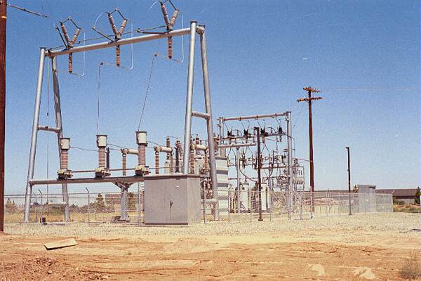
The substation transformer has a base rating of 12 MVA and can be loaded up to 17.9 MVA with the use of fans on the radiators. The substation is fed with a nominal voltage of 115 KV from PG&E�s Riverbank Substation over the Hershey Tap Line. The transmission line is attached to the A-Frame incoming structure. Power flows from the transmission line through a set of PG&E switches located at the top of the A-Frame and then through the PG&E metering devices located at about the middle of the A-Frame. From the PG&E metering devices, power flows through an electrically operated S&C Circuit Switcher to the high side of the transformer.
The transformer steps the voltage down to a nominal 17.2 KV. The secondary of the transformer is connected to a set of voltage regulators. The voltage regulators can regulate the voltage +/-10%. There are voltage regulator bypass switches, which can be used to bypass a particular regulator while it is in service. The power flows from the voltage regulators through a set of metering units to an automatic recloser that feeds all the plants. The recloser momentarily interrupts overloads and ground faults and then tries to reclose up to four times before locking out. There is also a recloser bypass switch to bypass the recloser while it is in service.
A station power transformer is connected to the secondary side of the transformer. The station power transformer is used to power lights and loads inside the substation. It may not be used to power any loads outside the substation. For example, a temporary extension cord may not be run from the substation to power tools located outside the substation.
The substation has a variety of protection schemes. The high side of the transformer is protected by four time overcurrent/instantaneous relays. Three of the relays are used to monitor the phases and one is used to detect a large unbalance current. The low side of the transformer is protected by four time overcurrent relays. Three of the relays are used to monitor the phases and one is used to detect ground faults. The transformer protection detects excessive winding and oil temperature and sudden pressure inside of the transformer tank. The differential relay protects the entire substation. It measures the power flowing into the substation and compares it to the power flowing out of the substation. If a large amount of power is lost inside the substation, the differential relay will operate. The primary purpose of the differential relay is to detect internal faults inside the transformer or voltage regulators. Lastly, the recloser has it�s own built in overcurrent and ground fault detection for problems outside the substation.
The PG&E Metering Cabinet is located outside the substation. The door has a dual lock so that either the customer or PG&E can go inside to read the meter.
Communications to the Substation is done via a fiber optic cable. Two telephone lines and one RS-485 data line are transmitted over the fiber optic line. One telephone line is for the customer�s use and the other phone line is for PG&E�s use. The RS-485 data line is for the power monitoring system.
Fiber optic communication was chosen so that complete isolation could be achieved. A fault in the substation would cause a Ground Potential Rise (GPR) in the substation as compared to a point outside the substation. In other words, a GPR in the substation could injure someone using a telephone or computer in the plant if traditional communications were used.
The Power Monitoring system consists of a Power Measurements 7700ION and a 3800 RTU in the substation along with a Power Measurements 3720 at the Cannery, the Can Plant and the Lagoon. The data from each of these devices is transmitted over the fiber optic line to a computer in the boiler control room. Power quality, alarms, trip statues and temperatures are monitored. The power monitoring system also controls the two stage capacitor bank in the substation.
The computer in the Boiler Control Room collects all of the power monitoring data. This data contains the power quality information, substation alarms, trip statuses and temperatures. Billing information is also recorded from the PG&E meter and compared to the customer�s metering in the Substation. Usage information for the Cannery, the Can Plant and the Lagoon are recorded and the percentage of usage is calculated so that the PG&E bill can be properly allocated.
Only authorized personnel should enter the substation. Nobody should ever go into the substation alone. Routine maintenance and service to the substation should only be done by qualified personnel trained in medium and high voltage wiring.
On a weekly basis, a quick walk through of the substation should be conducted. On the transformer, one should check the oil temperature, winding temperature, oil level, nitrogen pressure and look for obvious oil leaks. Under normal operating conditions, both the oil and winding temperatures should read below 70 degrees C. Under fully loaded conditions, the winding temperature might read as high as 90 degrees C. The nitrogen pressure gauge should read between three and five P.S.I. The oil level should read about medium and shouldn�t change unless there is a leak.
The voltage regulators should also be inspected. Open the voltage regulator control cabinet and verify that the Auto/Remote switch is in the Auto position and that the Power switch is in the Internal position. Press 9 on the keypad to see the load amps. Look at the yellow arm on the gauge at the top of the voltage regulator and note the position of the tap. Each of the three voltage regulator taps should be within four positions of each other. Lastly, check for any oil leaks.
The recloser should be inspected for any oil leaks. Open the recloser control cabinet and verify that the following switch positions are selected: Ground Trip Normal, Normal Reclosing, Supervisory On and Normal Trip. Press the battery load test button to test the internal battery.
There are three pole lights in the substation. The two lights facing away from the road are operated by a switch on the pole and should be tested. The light facing the road is operated by a photo-cell and should observed every evening. If the light doesn�t come on at night, it could indicate a loss of A/C power inside the substation and the problem should be corrected immediately.
Inside the relay cabinet, one should verify that the red lights for the S&C Circuit Switcher and the Recloser are all on. The differential bypass switch is only for testing purposes and should normally be in the off position.
Inside the battery cabinet, one should verify that the batteries are charging and that the battery voltage is around 125 VDC. The batteries should be checked for any leaks.
Before putting the substation into or out of service, it is necessary to contact PG&E Tesla Substation. This telephone number is posted below the S&C Circuit Switcher control switch.
All operation of the substation should be done from the relay control cabinet.
Verify that the S&C Circuit Switcher and the recloser are in the open position. A green light indicates that the particular device is open.
Verify that the differential relay bypass is in the off position. In the on position, this switch bypasses the trip circuit of the differential relay for testing on-line. It is necessary to turn the differential bypass on if the recloser is bypassed.
Verify that the 86 and 86T lockout relays are not in the trip position. The high side time overcurrent/instantaneous relays, the differential relay, the low side ground fault relay, the transformer sudden pressure protection and the transformer temperature protection trip the 86T lockout relay. The 86T lockout relay trips both the S&C Circuit Switcher and the recloser. The low side time overcurrent relays trip the 86 lockout relay. The 86 lockout relay trips only the recloser. If a lockout relay trips, take notice of which device caused it to trip. The faulted relay will display a red flag. Correct the problem and reset both the faulted relay and the lockout relay.
Verify that the PG&E switches at the top of the A-Frame structure are in the closed position. PG&E are the only ones who can operate this switch.
Verify that the regulator Auto/Remote switch is in the Auto position and that the Power switch is in the Internal position.
To energize the transformer, call PG&E Tesla Substation and turn the S&C Circuit Switcher knob to the close position. The blades will close first and then the bottles will engage. After a successful closure, the red light will illuminate. The transformer will hum loud for about 30 seconds. Wait for at least two minutes before putting any load on the transformer.
To energize the plant, open all main disconnects. Turn the recloser knob to the close position. After a successful closure, the red light will illuminate. Now close all main disconnects in the plant.
It is not possible to close the recloser with the S&C Circuit Switcher in the open position. Conversely, it is not possible to close the S&C Circuit Switcher with the recloser in the closed position.
If a fault occurs outside the substation and the recloser cannot successfully clear the fault, it will lockout. However, it will not trip the 86 or 86T lockout relay. If the recloser is open, the S&C Circuit Switcher is closed and both lockout relays are not in the trip position, check the recloser control panel for the trip condition. Correct the problem and close the recloser as described above.
The D.C. Lost Alarm consists of a siren mounted on the top of the light pole in the substation. If this siren is ever audible, it means that the substation has lost the D.C. control power. Most of the substation protection is controlled by D.C. power. This problem should be corrected immediately.
There is 3600 KVAR of power factor correction capacitors installed on the 17.2KV system. A fixed bank of 1200 KVAR is installed on the pole by the Can Plant and two stages of 1200 KVAR each are installed in the substation. The control knobs for the capacitors in the substation have three positions; Auto, Trip and Close. In the Auto position, the power monitoring system controls that particular back of capacitors. In the Trip position, the capacitor bank stage remains open. In the Close position, the capacitor bank stage remains closed. The substation capacitor bank has a main disconnect that is hand operated.
Any of the three regulators or the recloser can be bypassed without interrupting service to the plant. To bypass a regulator, open the control panel and put the regulator Auto/Remote switch in the Manual position. Use the Raise/Lower Switch until the Neutral Light is illuminated. It is now safe to bypass the regulator. Using a hot stick, pull the regulator bypass switch all the way down. To put the regulator back in service, again make sure that the regulator is in the Neutral position, the power switch is set to Internal and the Auto/Remote switch in set to Manual. Using a hot stick, push the regulator bypass switch all the way up. Once the control passes the diagnostics, set the Auto/Remote switch to Auto.
To bypass the recloser on-line, make sure that the fuses are installed in the bypass units. Using a hot stick, push each fuse holder into the closed position. Open both the source and load disconnects with a hot stick. To put the recloser back into service, make sure that it is in the closed position. The recloser requires that line voltage be present on the source side to close remotely. To manually close the recloser, follow the instructions in the recloser manual. Close both the source and load disconnects with a hot stick. Lastly, pull the fuse holders down.
In the event that the substation is not operational, the use of the emergency Back-Tie must be coordinated with PG&E. Completely de-energize the substation. Open both the S&C Circuit Switcher and the recloser. Next open the air switch on the first pole outside of the substation. PG&E may put their own lock on this switch. Close the 600A solid blade disconnects in front of the Emergency Back-Tie Recloser. PG&E will then close their air switch by the railroad tracks. Make sure that all main disconnects are open and then close the Emergency Back-Tie Recloser. The main disconnects can now be closed.
To put the substation back into service, open the Emergency Back-Tie Recloser and pull open the 600A solid blade disconnects in front of the Emergency Back-Tie Recloser. PG&E will then open their air switch by the railroad tracks and remove the lock on the first pole outside of the substation. Close the air switch on the first pole outside of the substation. Put the substation back into service as described previously.